Weld Symbols—AWS A2.4 Quick Guide
Weld Symbols—AWS A2.4 Quick Guide
Shop-friendly reference to weld symbols per AWS A2.4: what they are, how to read arrow/other side, and the core components you need on drawings.
What you'll learn
- Read and interpret AWS A2.4 weld symbols
- Understand arrow side vs other side placement
- Identify basic and supplementary weld symbols
Quick facts
- Reference line carries all the info
- Below line = arrow side, above = other side
- Tail is optional for process/spec notes
Basic Joint Types {#joints}
Before diving into symbols, you need to understand the five basic joint configurations. These are how two pieces of metal come together before welding.
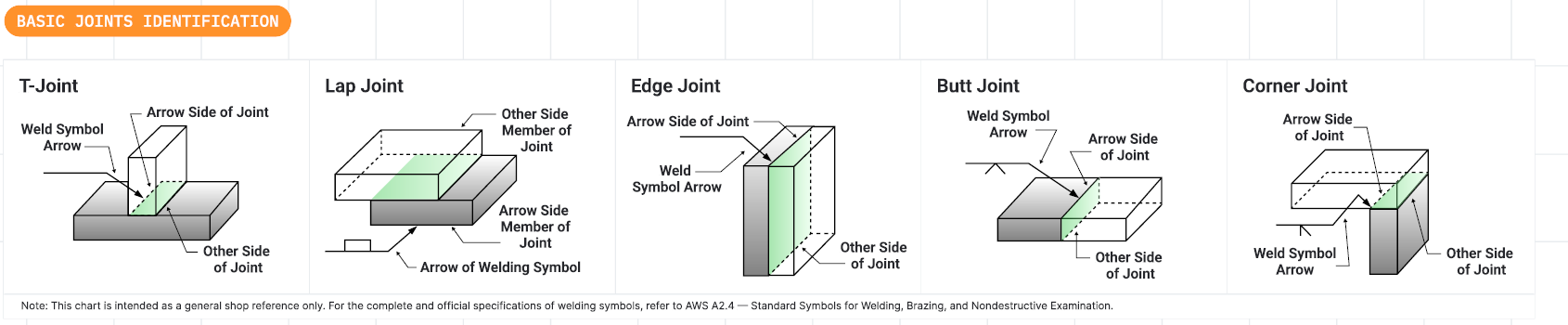
The joint type determines which weld symbols apply and how the weld will be executed. Each joint has specific applications based on load requirements, accessibility, and material thickness.
What Are Weld Symbols? {#what-are}
What Are Weld Symbols?
Weld symbols are standardized graphics placed on engineering drawings to communicate exactly how a weld should be made. They serve as the universal language between three key groups:
Design Intent — Symbols tell the welder exactly what type of weld, what size, and where to place it without ambiguity. This eliminates guesswork on the shop floor.
Fabrication — Welders can read the symbol and know exactly what process, size, and technique to use for each joint. This ensures consistent quality across all welds.
Inspection — QC inspectors use the same symbols to verify the weld matches the design specification. This provides clear pass/fail criteria.
The welding symbol system is defined by AWS A2.4 (American Welding Society) and is recognized worldwide.
Weld symbols are the universal language between design, fabrication, and inspection teams. Everyone reads the same drawing and understands exactly what's required.
How to Read Weld Symbols {#how-to-read}
How to Read Weld Symbols
The core of every welding symbol is the reference line, a horizontal line that serves as the base for all weld instructions, including type, size, and length. (see image right)
A welded joint typically has two sides, so there are two possible locations for welds. For instance, in a T-joint between two steel plates, welds might be required on either side of the vertical plate. The welding symbol distinguishes these sides using the arrow side and the other side convention:
- Instructions placed below the reference line apply to the arrow side of the joint.
- Instructions placed above the reference line apply to the other side of the joint.
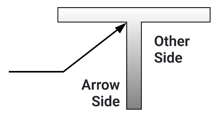
The arrow points to the joint. Information below the reference line tells you what to do on the arrow side. Information above tells you what to do on the other side.
Symbol Components {#components}
A complete weld symbol can include many elements. Here's the breakdown of what goes where.
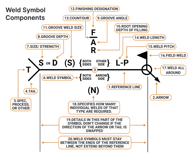
Weld Symbol Components
- Reference Line: Main line where weld info is placed.
- Arrow: Points to joint location for weld.
- Arrow Side / Other Side / Both Sides: Specifies weld location relative to arrow.
- Tail (T): Optional notes like process, specs, or codes.
- Spec, Process, or Other: Text in tail with extra instructions.
- Weld Symbol: Shape indicating weld type (e.g. fillet, groove).
- Size / Strength (S or D): Size or strength of weld (e.g. leg size, throat).
- Groove Depth: Depth of groove prep.
- Groove Angle: Angle between groove faces.
- Root Opening / Fill Depth: Gap at root or how deep to fill.
- Groove Weld Size: Throat size for groove welds.
- Finishing Designation: Specifies weld finish method (e.g. grind, machine).
- Contour: Final weld surface shape (flat, convex, concave).
- Weld Length: Length of each weld segment.
- Weld Pitch (L-P): Spacing between welds.
- Field Weld: Weld done on-site, not in shop.
- Weld All Around: Weld goes completely around joint.
- (N): Number of identical welds required.
- Details Don't Change with Arrow Direction: Symbol info stays valid if arrow flips.
- Symbols Stay Between Reference Line Ends: Symbols must fit within reference line limits.
The tail is only added when you need to specify welding process (like GMAW, SMAW), specification references, or special instructions. If not needed, leave it off to keep the symbol clean.
Basic Weld Symbols {#basic-symbols}
These are the fundamental shapes that represent different weld types. Each symbol corresponds to a specific weld cross-section.
Fillet Weld
The most common weld. Triangle shape indicates a triangular cross-section joining two surfaces at an angle.
Groove Welds
V, U, J, bevel, and square groove symbols. Used when pieces are butted together and need full penetration.
Plug/Slot Welds
Circle or rectangle with dimensions. Weld through a hole in one piece to join to another below.
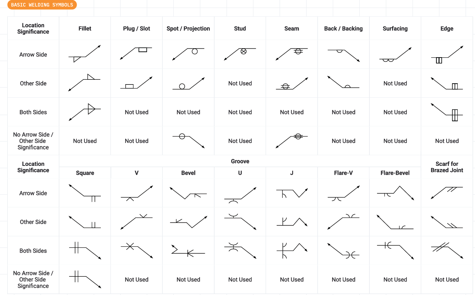
Each symbol shape corresponds to the cross-section of the finished weld. Learn these shapes and you can read any welding drawing.
Supplementary Symbols {#supplementary}
These modify the basic weld symbol to add more information about how the weld should be finished or applied.
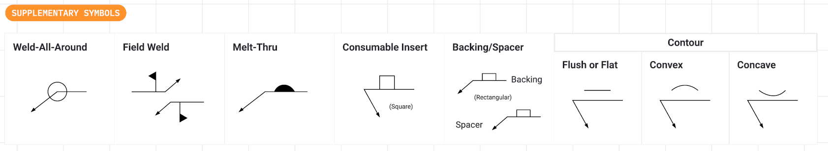
Supplementary symbols are added to the basic weld symbol to specify finish, field vs shop, and special requirements.
Quick Reference Table {#reference}
Here's a handy reference for which symbols can appear on arrow side, other side, or both.
| Weld Type | Arrow Side | Other Side | Both Sides |
|---|---|---|---|
| Fillet | ✓ | ✓ | ✓ |
| Square Groove | ✓ | ✓ | ✓ |
| V Groove | ✓ | ✓ | ✓ |
| Bevel Groove | ✓ | ✓ | ✓ |
| U Groove | ✓ | ✓ | ✓ |
| J Groove | ✓ | ✓ | ✓ |
| Plug/Slot | ✓ | ✓ | — |
| Spot/Projection | ✓ | ✓ | — |
| Seam | ✓ | ✓ | — |
| Stud | ✓ | — | — |
| Surfacing | ✓ | — | — |
Shop Tips {#tips}
Arrow Side Rule
Information below the reference line = arrow side of joint. Always.
Keep Symbols Clean
Place symbols between reference line endpoints. Don't let them extend past.
Tail Usage
Only add the tail when you need process/spec callouts. Otherwise, omit it.
When in Doubt
Refer to AWS A2.4 standard. It's the ultimate authority on symbol interpretation.
Final Thought
Weld symbols are the universal language of metal fabrication. Once you learn to read them, you can work from any drawing, anywhere in the world. The system is logical—arrow side below, other side above, and symbols that look like the weld cross-section they represent.