Fit—clearance, interference, transition
Fit—clearance, interference, transition
Understanding how parts actually fit—clearance, interference, transition, and why "H7/g6" isn't just a weird robot code.
What you'll learn
- Decode H7/g6 and other ISO 286-2 callouts
- Understand clearance, transition, and interference fits
- Pick the right fit for your manufacturing process
Quick facts
- Hole-basis system is most common
- IT grades define tolerance width (lower = tighter)
- H for holes, h for shafts
First: What's a Tolerance Zone?
Every real-world part has variation—no hole is exactly 10.000000 mm, and no shaft is perfectly round. That's where tolerances come in.
Think of a tolerance zone like a football goalpost. Your target dimension is the center, but as long as the actual part lands anywhere between the uprights—the upper and lower limits—it's good. Manufacturing isn't perfect, but if you stay in the zone, the part passes.
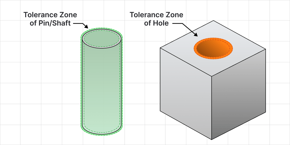
Shafts Go in Holes. Usually.
The ISO 286-2 system primarily deals with features of size—typically shafts fitting in holes, though it also applies to keys, keyways, etc.
Clearance Fit
There's always space between the shaft and the hole, even in the worst-case tolerance scenario—parts slide or spin freely.
Transition Fit
Sometimes clearance, sometimes tight—it depends where the tolerances land. These are often used when you want a snug but still removable connection.
Interference Fit
There's never space—one part is always larger than the other, so force (or heat/cold) is required to assemble them. These joints are meant to stay put.
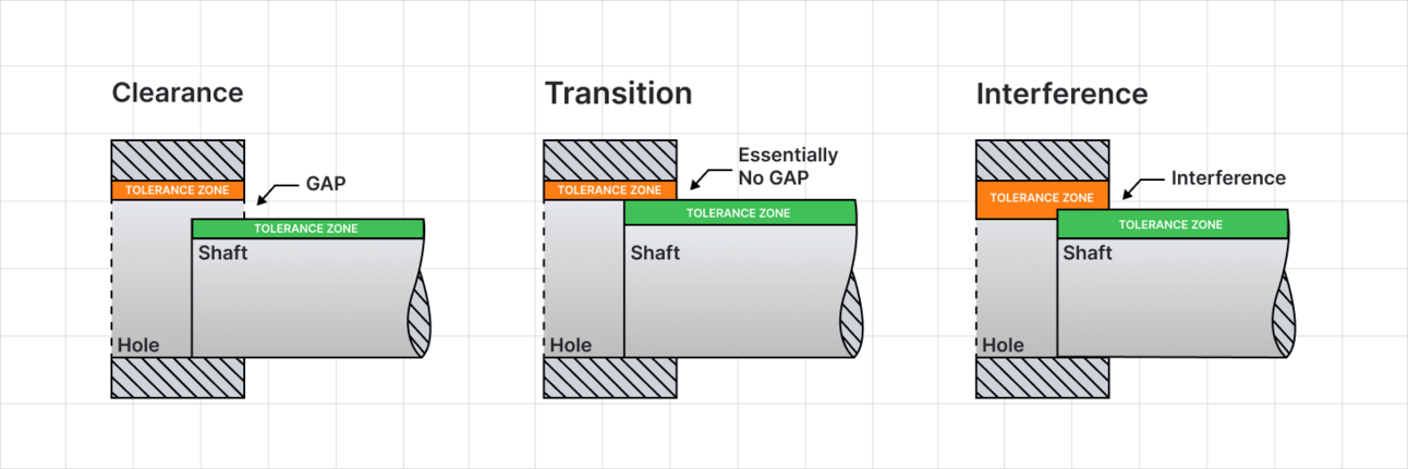
A ⌀4.00 mm shaft in a ⌀5.00 mm hole? Clearance. A ⌀5.25 mm shaft in that same hole? Interference. The fit depends on how close the tolerance zones are, not just nominal dimensions.
Shaft-Basis vs Hole-Basis
In most cases, you have more control over one part than the other.
Shaft-Basis System
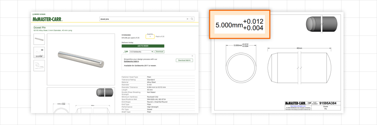
If you're designing around pre-bought dowel pins, you're using a shaft-basis system—you have to tweak the holes to match the pin tolerance.
Hole-Basis System
If you're designing a custom shaft to fit a purchased bearing, you're working with a hole-basis system.
Most designs use a hole-basis system because it's easier to machine shafts with tight precision than holes. Shafts can be turned or ground accurately, while holes are harder to control and adjust after machining.
Allowance vs Clearance
Let's say you have a dowel pin and you're reaming a hole for it:
Allowance (Minimum Clearance)
The minimum guaranteed space between the largest pin and the smallest hole—what you design for to ensure a fit.
Maximum Clearance
The maximum space between the smallest pin and the largest hole—this can mess up fit if too big.
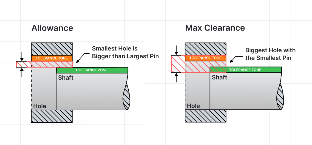
If the clearance gets too large (or too small), the fit might fail. You can reduce this variation by tightening your tolerance zones—but that usually means changing your process or paying more for precision parts.
What's Up With H7/g6? {#h7g6}
This is the core of the ISO 286-2 system. It's also the most confusing—until you break it down.
Letters
Indicate the position of the tolerance zone relative to the nominal size (A → ZC)
Numbers
IT grades define the width of the tolerance zone (1-18)
Smallest size is the nominal, but it can be larger
Size is slightly smaller than nominal
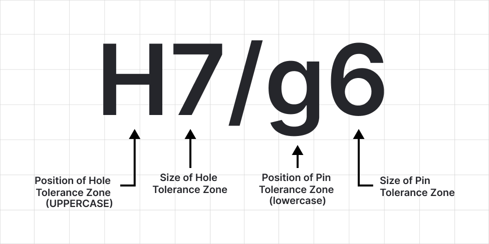
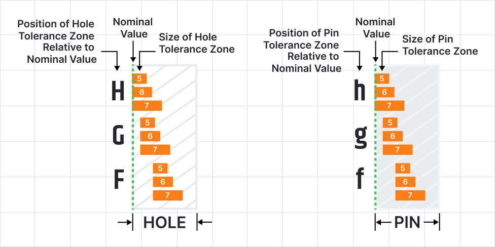
Key Insight
The "H" position is super common because it includes nominal value as one of the tolerance zone limits, which makes it versatile for both hole- and shaft-basis fits.
- Holes: H → the smallest the hole can be is the nominal size
- Shafts: h → the biggest the shaft can be is the nominal size
Note: Uppercase letters = holes | Lowercase letters = shafts
IT Grades: What Can You Actually Achieve? {#it-grades}
We just talked a lot about the letters of "H7/g6", let's look more closely at the numbers.
Every manufacturing process has limits—it can only produce parts within a certain level of precision. That level is defined by something called the International Tolerance grade, or IT grade.
The lower the number, the tighter the tolerance. And tighter tolerances usually mean more time, more tooling, and more cost.
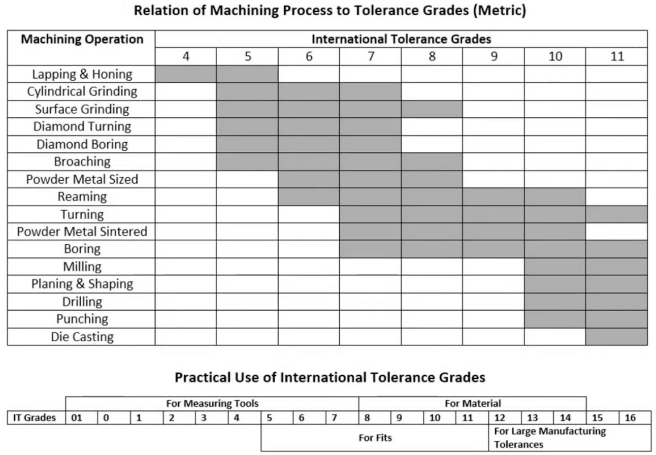
Chart showing typical IT grades achievable by different manufacturing processes
Before you spec a fancy H5/p5 interference fit, ask yourself:
Can my shop actually hit those numbers?
Designing to an IT grade your process can't reliably achieve means scrapped parts, blown budgets, or a very grumpy machinist.
A good rule: Pick the fit based on your process, not the other way around.
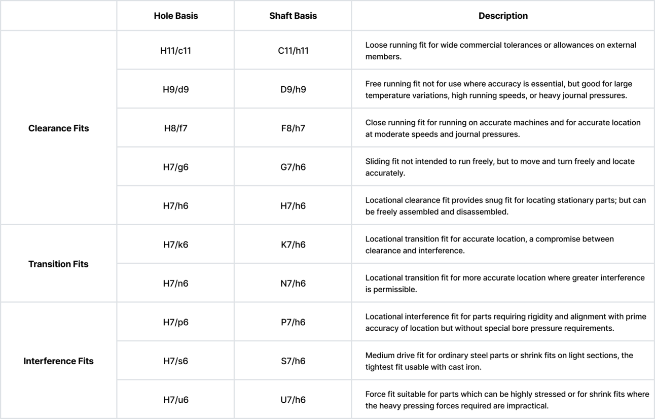
Real Fit Examples {#examples}
Let's say you're using a 12.7 mm (½ inch) dowel pin with an h6 tolerance—this is a common spec for precision ground pins. The h6 designation means the pin's diameter is slightly under the nominal size, but never over it, keeping it consistent and easy to match with a variety of hole tolerances.
Now let's look at how that pin fits into different hole tolerances:
You can shake the pin around
Good for locating, but still removable
May require a light mallet
Bring out the press
As you can imagine, some hole/shaft combinations are less practical. As a result many preferred fits charts have been made. Below I'll include one I made from the ISO 286-2 guidelines.
How to Use the ISO 286-2 System {#how-to}
Instead of manually calculating every min/max size for every part, you:
Identify your nominal size
Start with the basic dimension you're targeting
Choose a fit
Sliding, interference, light press, etc.
Use the ISO tables
Like the ones above, to find the correct zones
Specify the fit
As hole_zone/shaft_zone (e.g., H7/g6)
Pro Tip
Machinists can look up the exact ranges—or you can include the limits in your drawing to make everyone's life easier.
Final Thought
The ISO 286-2 system of fits and tolerances can feel arcane at first, but once you get the hang of it, it's wildly useful. With just a couple letters and numbers, you can communicate exactly how parts should fit—and whether that press fit is going to require a hammer, a mallet, or a full-blown hydraulic setup.
Other Resources {#resources}
References {#references}
Oberg, E., Jones, F.D., Horton, H.L., Ryffel, H.H. (2016). Machinery's Handbook. 30th edition. Industrial Press Inc.
Oberg, E., Jones, F.D., Horton, H.L., Ryffel, H.H. (2012). Machinery's Handbook. 29th edition. Industrial Press Inc.
ISO 286-1 (2010). Geometrical product specifications (GPS) - ISO code system for tolerances on linear sizes - Part 1: Basis of tolerances, deviations and fits.
ISO 286-2 (2010). Geometrical product specifications (GPS) - ISO code system for tolerances on linear sizes - Part 2: Tables of standard tolerance classes and limit deviations for holes and shafts.
ANSI/ASME B4.2 (1978). Preferred Metric Limits and Fits.
Credit: Original article on Drafter